1997 was the year that Anungoday's gasoline outboard engine said "rebuild me NOW!" While we were waiting for a chance to do that, we picked up an electric trolling motor without a whole lot of shopping around. Some other members of the Lafayette Sailing Club, with even larger boats, have had no trouble getting in and out of the harbor in most weather with modest motors around 30 pounds of thrust, so that's what we bought: a MotorGuide QS270.
It got us through that season just fine, sitting on Anungoday's transom motor mount, the position vacated by the ailing engine. Once the engine was repaired, though, we faced a dilemma: There's only one motor mount bracket on Anungoday's transom. The little motor is our first preference any time it is enough, and it has been plenty for getting around in Lake Freeman in any weather we've seen so far. It's virtually noiseless, odorless, and delightfully convenient. Turn the switch and the boat moves.
On the other hand, it's very nice to have 8 HP ready to use at the pull of a rope. Trying to share a single motor mount would require dismounting one and mounting the other when we need it. That is, leaning from the cockpit out over the drink and trying to lift or place a 50 pound engine that we can ill afford to replace. If we're doing that because we suddenly need the other machine, then the conditions are probably especially bad for doing outboard ballet on the edge, and it would probably be one of the worst times to actually lose the engine. That just didn't sound like a good plan.
It would be just peachy to have both ready to use at all times. Turn the switch and use the motor. Pull the rope and use the engine. But there isn't even any room on the transom for another motor mount. Between the Chrysler 8, the rudder, and the boarding ladder, there's no place to put another tall thing with a propeller and not have it foul on something else.
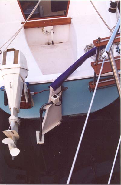
The electric motor could go on the rudder!
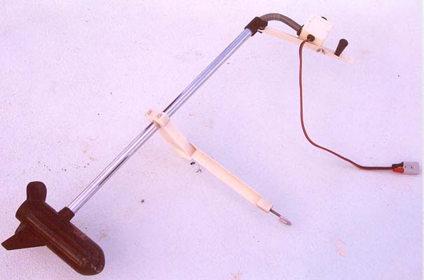
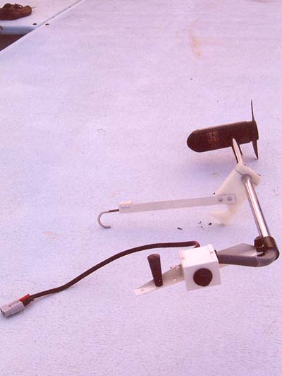
So we took off the big ugly stock head and handle of the QS270 (it's nothing but a big pretentious plastic enclosure for a lot of air, a small rotary switch, and a relay...and even the relay's an unnecessary gimmick), and we took off the even bigger and uglier universal raise lower twist lock fits everything tiltawhirl transom bracket. We don't need a steering handle or twist bracket, the motor goes where the tiller points. We don't need a raise/lower/tilt/clamp bracket. Once we took off all the extraneous hardware, what's left of the motor weighs about six pounds, and at that rate when we don't want it dragging in the water we slip it off the rudder, unplug the cord, and toss it below.
A six pound motor exerting 30 pounds of thrust puts a resultant force on the rudder of about 31 pounds aimed forward and very slightly down. We figure the rudder and its cast bronze gudgeons can handle the extra load, especially as the electric motor is most useful in fair weather when the hydrodynamic forces on the rudder are far milder than the worst case.
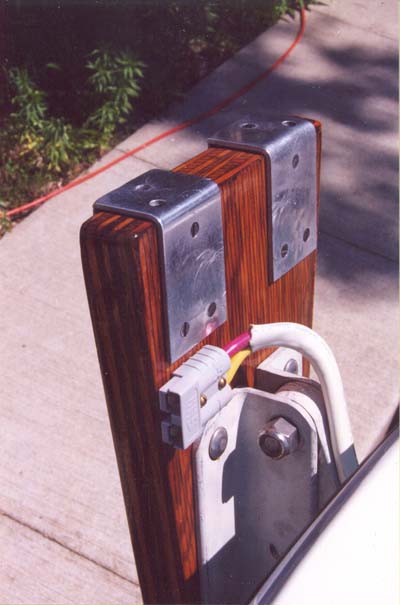
The bottom part of the bracket, which wraps around the leading and trailing edges of the rudder, just slips over rudder from the side, up high where it's narrow, and slides down the widening rudder until it is tight. At that point the holes in the top bracket slip over the rudder's upper gudgeon bolts and the motor can't slip off. The tapered black handle shown can be unscrewed from its storage stud and screwed down on the exposed end of the gudgeon bolt to hold the bracket securely in place.
The "hook," shown on the bottom bracket for holding the leading edge of the rudder, is a stainless U-bolt with one leg amputated. Threaded into a tapped hole in the small nylon block, it can be turned to fine-adjust the fit of the bracket.
All that's left of the original overdone control head is the original switch mounted in a small aluminum box. It is mounted within reach of the original column wiring, four wires that were just unclipped from the switch, threaded out of the old control head and into the new box, and clipped back to the switch again. The two-conductor power cable was clipped as short as possible (the gauge seems light for 36 amps) and fitted with a 50-amp rated SMH plug mating with an 8-gauge cable we attached to the battery with a 40 amp ignition-protected breaker.
Our choice of a 30 pound thrust motor for a 20 foot, 1600 pound sailboat was a bit arbitrary; it was an unplanned and unbudgeted bid to save a sailing season when the gasoline engine went south, and they had a QS270 at the marina next to the sailing club. It has worked superbly for us on Lake Freeman in the mild weather we've been sailing in, but if you have the time and budget to shop for a while and make a planned purchase, you might want to look at larger motors too. On the other hand, our whole plan is to have electric and gasoline propulsion available, so going big and heavy on the motor might make less sense than keeping the cute six-pound contraption we can slip on the rudder without straining, and pulling the rope on the Chrysler when the motor isn't enough.
One thing to be said for slightly larger motors is they are available with Electronic Variable Speed controls, whereas smaller motors like ours tend to have a simple five-position switch. If I had an opportunity to do this over with more time and budget, I would seriously consider an electronic variable speed unit, for two reasons:
A simple five-speed unit like ours contains resistors used to obtain the lower speeds. The resistors are lengths of very fine wire wound into coils inside the motor housing, where they might be mistaken for motor windings. On all speeds except high, the resistors are switched into the circuit in various combinations, with two effects:
Point (2) is sometimes misunderstood to mean the resistors "burn off" all the extra power compared to the high speed power draw. They don't; see point (1). However, they do convert a few odd watts into warm water, and on a sailboat where charging is a hassle, that's enough to make you go "hmm." It could be more efficient if you could somehow leave the motor on high, where all the power drawn goes to the motor, and just switch it on and off really fast to get the amount of power you want. That would be pulse-width modulation (PWM), and it could be how the electronic variable speed units work. I would like to think so.
A recent TSBB posting by Charles Brennan suggests that even some so-called electronic speed controls just use solid state switches to play the same old resistance game, and I've seen enough stupid marketroid tricks to believe it. I can only hope that they aren't all like that. I'd guess the ones that say "infinitely variable speed" probably use PWM, though something that just says "electronic control" might be a marketing gimmick. Would have to take them apart to see for sure.
The discrete speed, resistance units like ours have several wires running from the control head down the column; ours has four, one for each of the two resistors located down in the motor housing, plus one direct to the motor and a return. These are all heavy gauge, power-carrying wires, and the speed control knob is on a largish, 40 amp rated rotary switch. It's a nice simple design but it limits the control knob to being placed on or near the top of the column. Otherwise, unwieldy multiconductor heavy-gauge cables would come into the picture and, because they are carrying the full motor current, the extra length would be a detriment.
A true PWM unit might well have only two wires between the control circuit and the motor; that's all it needs. A PWM made into a rudder clip-on like ours would need nothing on top but a two-conductor cable and plug, not even the little switch box we have on ours. The electronic circuitry could be installed safe inside the boat, on a short, direct path between the battery and the motor connection.
The speed-control knob on a PWM motor is probably a small potentiometer carrying only a small signal current back to the PWM electronics. Though it's probably soldered to the circuit board at the factory, it could be removed and placed anywhere on the boat, connected back to the circuit board with a small, inexpensive, light gauge interconnect cable. Because it carries only a signal current, the cable length would be unimportant. A creative woodworker, for example, might laminate a tiller with a tiny speed knob in the end. The possibilities are bounded only by the imagination.
Here's someone else's solution to the same problem:
Jim's "Modder"