Fun with the Ensenada 20 Swing Keel
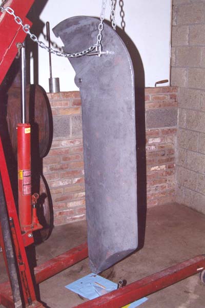
Or, what do I do if my keel looks like this:
Removal and Installation
First order of business is getting that puppy out.
What AM I getting into?
The Ensenada 20 keel is a solid, 550 lb iron casting.
For comparison, that's nearly twice as heavy as the engine in Anungoday's
tow vehicle, and if you don't work in heavy industry, it might be way heavier
than any object you've handled before.
It's also narrow with a high center of gravity.
Holding it upright feels deceptively easy as long as it stays upright, but let
it lean an inch to one side and you'll wrestle to save it.
Two inches and you might not save it.
Be careful, and avoid being anyplace it might fall.
The E20 has essentially the hull and keel of the Balboa 20, so the
access and repair techniques from Cliff Unruh's
Common Balboa 20 Repairs
page mostly apply. The weasel words reflect one
small but important change to the hull.
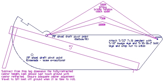
The brochure for the Balboa lists a draft of 1 foot, 9 inches with the keel up.
The same figure in the Ensenada brochure is 1 foot even.
The difference lies in how the keel is mounted to the hull.
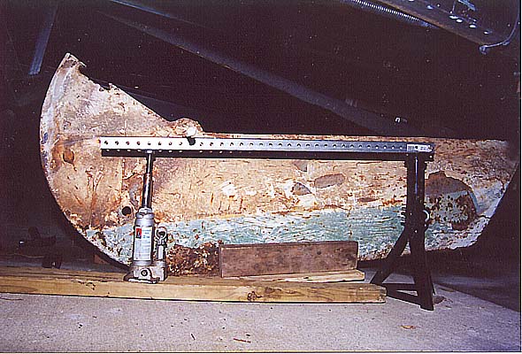
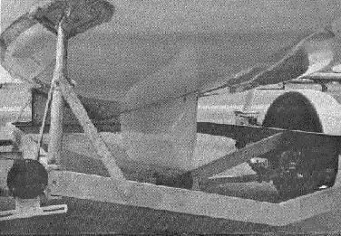
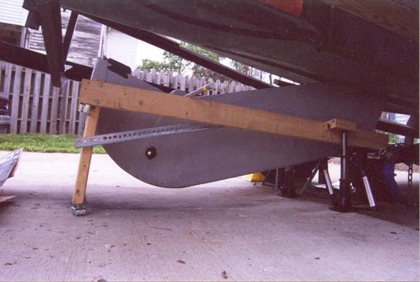
If you look closely at the gnarly picture above, you will see that there are two
pivot holes drilled through the keel.
The upper one (with the rod through it, in the picture) is for the 1'9"-draft
boats.
The lower hole (look just to your left of the bottle jack, near the bottle top)
is used as the pivot in the 1'0"-draft Ensenadas.
You can see that in the deeper-draft boats, almost all of the keel is carried
below the hull; the keel trunk in a Balboa is little more than a bump in the
floor.
In the picture from the Ensenada brochure, you can see that the keel trunk
(a/k/a the Great Wall of Ensenada) is as tall as the settees, and the retracted
keel is carried mostly above the hull bottom.
The difference carries over into the trailer design.
The Balboa trailer has tall bolsters and holds the boat high to clear the
mostly-exposed keel.
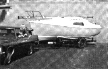
The Ensenada trailer carries the boat bottom 9 inches nearer the ground, nestled
well down between the tires.
Cliff's keel removal procedure for the Balboa calls for lifting the boat high
enough to sneak the keel out below the hull bottom and above the ground and
trailer roller.
It's the same for a shallow-draft Ensenada only more so.
Before the keel can escape the keel trunk, it has to come 9 more inches out
the hull bottom, which is 9 inches nearer the ground to begin with.
Our procedure here is an attempt to get the necessary height without lots of
repetitive jacking and blocking, and without having a boat teetering crazily
above our heads.
The gist of our technique is that the tallest part of the keel is forward so
it's mostly the bow of the boat that needs to go up. We raise the trailer
tongue way in the air, but leave the wheels on the ground for stability.
For most of the procedure the trailer is supported on four points: a tall stand
at the tongue, both wheels on the ground, and the center of the aftermost cross
member, which is also on the ground.
The boat looks like it's ready for take-off.
The stern of the boat also needs to be lifted a foot or so off the bunks.
There has to be some safe and reliable way to roll the keel out from under the
trailer (to where a hoist can pick it up) and back under for installation, while
keeping it upright.
If it's allowed to flop onto its side, besides the potential for injury, it may
have to be levered up and rods put beneath it "Egyptian style" to roll it
some place where a hoist can be attached to set it back upright.
Materials used
These materials and procedures worked for us.
Your safety is your responsibility; it's up to you to decide if any
of our material, design, or procedure choices will be safe for you.
We hate having to say that, but you know how things are.
- 4
- Trailer wheel chocks.
- 1
- Portable engine hoist, used for lifting the trailer tongue, lifting the
stern, and of course the keel itself.
Very useful.
Can be rented if you don't have or buy one.
- 1
- Heavy tow strap, or other suitable sling for lifting the stern.
- 1
- Tall adjustable stand to hold the trailer tongue in a raised position.
We used two 3' lengths of 1-1/4" x 1-1/4" perf tube (a/k/a tel-spar) inside
two 3' lengths of 1-1/2" x 1-1/2" perf tube, top ends bolted to the trailer
tongue to make a telescoping A-frame, fixed at the right length with 5/16"
bolts through the tubes.
The bottoms of the A were lag bolted to an 8" x 8" by 18" wood block we had
handy.
Your own available materials and design can be used for the stand, as long as
it's tall enough and you trust it.
Because the trailer axle will be moved aft, the tongue raised, and the stern
raised, design your stand for a lot more than the usual 10% tongue weight.
- 2 or 4
- Bottle or vertical screw jacks.
Two should work if you have enough jackstands, four will save time.
- 4+
- Adjustable jackstands.
- some
- 2x4 and 4x6 wood scraps, come in handy
- 1
- 3/8" x 2-1/2" bolt with nut and two 3/8" ID, 1/2" OD nylon bushings.
- 1
- Pivot bushing installation pilot tool.
A socket from a socket wrench set works fine if the size is right.
The one I used is a special socket I had lying around for GM brake caliper
bolts, with a narrow nose and nice smooth taper up to a 3/4" body diameter just
the same as the pivot bushing.
For installation, once you get the holes roughly aligned, tap the pilot tool in
from one side of the keel trunk until the wide part of the body has entered the
keel.
The holes are now aligned and you just drive the real pivot bushing through from
the other side until it comes through and knocks the pilot out.
- 2
- 3/4" solid steel round rods, at least 2' long.
- 8'
- 1/4" proof coil chain.
- 1
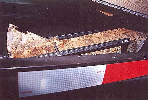
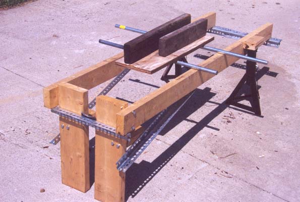
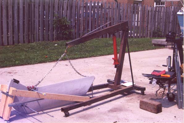
- Keel-O-Matic.
Wait! What's a Keel-O-Matic?
In the pictures at the top of this page, the keel is supported on a 3/4" steel
rod through a pivot hole, running on "rails" either side of the keel.
That was a last-minute improvisation while we took the keel out, but it worked
so well we turned the idea into the Keel-O-Matic in time to put the keel back
in.
The Keel-O-Matic serves to raise and lower the keel, hold it upright, and roll
it safely while it is on the ground.
The materials are 2x4 and 2x6 lumber, 1-1/2 x 1-1/2 steel angle, lag bolts, and
low profile, heavy duty refrigerator-freezer casters.
The aft end (where the keel weight is concentrated) runs on four casters, the
front end on two.
The casters are placed for a wide wheelbase to resist the keel's implacable
desire to topple sideways.
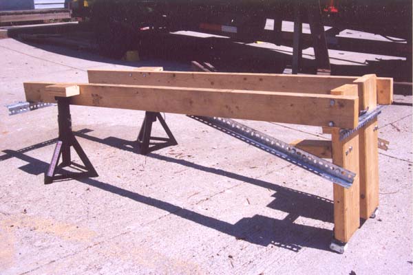
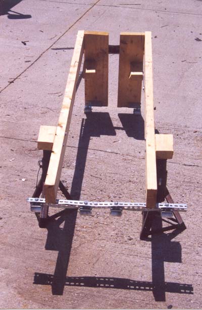
For transport, the keel hangs as low as possible in the Keel-O-Matic,
suspended by a steel rod through the top pivot hole, the forward edge against
the upper cross-piece of steel angle (you can see the felt pad, to protect the
bottom paint during installation), and the heavy aft end of the keel resting
directly on the aft cross-piece (protected by a piece of carpet not easily seen
in the pictures), supported by the four casters.
The forward curve of the keel skims a fraction of an inch above the ground,
enough clearance to roll the Keel-O-Matic without scraping the paint, but low
enough to sneak under the trailer frame without having to lift the trailer even
more ridiculously high.
You can get the critical dimensions of the Keel-O-Matic from this
CAD drawing (KeelOMatic.DXF).
If you do not have CAD software, check into the freeware
QCad.
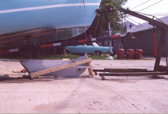
Removal
Our only pictures of the Keel-O-Matic in action were during installation, but
your first interest is probably removal, so we will show you the pictures
backwards.
-
Carefully mark the location of the axle brackets on both sides of the trailer.
You must be able to return the axle to exactly this position later for proper
trailer balance and wheel alignment.
- Jack up the rear of the trailer until the weight is off the wheels.
Loosen the axle U-bolts and slide the axle assembly aft as far as possible,
until the axle abuts the rear crossmember/keel roller.
Chock the wheels in this position and lower the trailer.
If you twisted or broke any U-bolts, don't panic;
a commercial truck parts shop (like Rowe Truck Equipment in our neck of the
woods) can bend new ones to match while you wait; we replaced all four for $18
including new nuts and washers, and you won't need them until you are all done
with the keel anyway.
- Attach the engine hoist to the trailer tongue.
Put a rubber mat, thin plywood, or
the like under the center of the aftermost trailer cross
member to protect the paint; at some point you'll probably raise the trailer
tongue past the point where this cross member hits the ground.
You won't be lifting the wheels off the ground, but shifting enough weight to
the cross member that the axle springs will extend. Make sure you check for wayward ladders and such that project down from the transom - you don't want to squish anything into the ground when you lift the tongue of the trailer.
No need to lift anything yet, though.
- Be sure the keel pendant is slack, keel weight taken on the trailer roller.
- At the start, neither keel pivot hole is accessible to put a support rod
through; you must support the keel entirely from below.
So, lay both rods across the Keel-O-Matic with the keel cradle on top,
with the keel resting in the cradle.
You'll have to imagine this setup in place under the keel, we forgot to take a
picture then.
This arrangement allows the cradle and keel
to roll fore-and-aft, not so important now,
but it will be for installation when you need to align the pivot holes.
The Keel-O-Matic/cradle should be taking the weight of the front of the keel.
If there is clearance, jack up the Keel-O-Matic until it takes the weight.
If there is not enough clearance to get the cradle in position, lift the trailer
tongue with the engine hoist just enough to clear, then let it back down just
until the cradle takes the keel weight.
- Inside the cabin, remove the keel pivot nuts and the 1/2" pivot bolt.
Place the 3/8"ID-1/2"OD nylon bushings in the ends of the stainless steel pivot
bushing, run the 3/8" bolt through the bushings, and snug the nut.
Use a hammer and drift against this bolt, not the pivot bushing itself, to drive
the bushing out of the trunk.
- Raise the trailer tongue with the engine hoist, lifting the
boat off the keel until the lower pivot hole is well below the hull.
About 10" below is good, or until you can just see the upper pivot hole, but
watch the after tip of the keel carefully; by raising the bow you are bringing
the after keel trunk down toward the tip of the keel.
Stop lifting before they connect.
- Support the trailer tongue at this height with the A-frame or other support.
Position the engine hoist to lift the stern of the boat with the tow strap under
the quarters.
Don't lift until you need to.
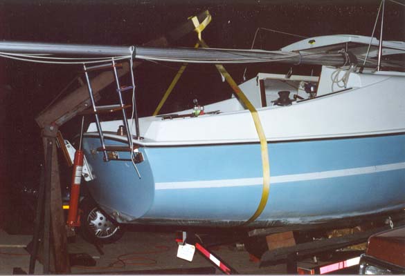
Note: we worried about fastening the strap somehow so it
wouldn't slip off the stern, but that didn't turn out to be a problem.
The hoist boom lifts in an arc, not straight up, so it pulls aft while lifting,
and the strap definitely slips aft just enough to stay below it,
but it never showed any
sign of slipping more than that.
It does make disconcerting noises as it takes up the strain, but did no damage
to the boat finish and as long as the strap is adequately rated there seems to
be no problem.
- Support the keel cradle with jacks side-by-side so the rods can be
removed from beneath it.
Run one of the rods through the lower keel pivot hole.
Jack the Keel-O-Matic up to meet it and take the weight.
Remove the cradle.
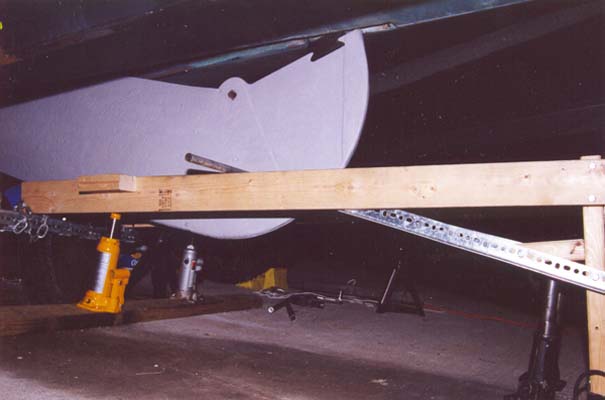
Lower the Keel-O-Matic until the forward tip of the keel can clear the trunk
moving forward.
Watch the after tip (which will go up) to avoid gouging the inside of the trunk.
Use the engine hoist to lift the stern as needed.
The Keel-O-Matic should be roughly level.
- Ease the keel pendant and allow the keel to roll forward on the trailer
roller and the Keel-O-Matic.
It would be nice to end up with the aftermost part of the keel's straight
leading edge resting on the carpeted after crosspiece of the Keel-O-Matic.
It might not work out exactly that way, so a little jockeying may be needed
later.
A sheet of tough thin plastic like those one-piece 3-ring binders over the
trailer axle and crossmember will protect the trailer paint.
- Place the other 3/4" steel rod through the upper keel pivot hole.
Place the cradle under the keel and support with jacks side-by-side.
With the tip of the keel clear of the trunk, the keel can now tip
sideways.
It wants to get you.
Use the jacks side-by-side as wide as possible for stability.
Also, if possible, please have one person hold the keel steady by the front edge
and the upper steel rod, while another person fiddles with the Keel-O-Matic and
removes the lower rod.
With the weight off the Keel-O-Matic, remove the lower steel rod.
Lower the keel cradle and/or raise the Keel-O-Matic until the Keel-O-Matic takes
the weight on the upper rod.
Remove the cradle.
- Lower the front of the Keel-O-Matic onto the casters.
-
Lower the rear of the Keel-O-Matic, allowing it to move forward so the tip
of the keel clears the trailer axle.
(We didn't have a floor jack with wheels, but it would be handy for this part.)
Ease the keel pendant as needed.
- When the after casters are on the ground, remove the jacks, disconnect the
pendant, and roll the Keel-O-Matic out from under the trailer.
Lower the stern so you can use the engine hoist to lift the keel from the
Keel-O-Matic, using the 8' of 1/4" proof coil chain as a lifting bridle attached
at the upper keel pivot hole and the pendant attachment hole.
Enjoy refurbishing your keel!
Note on rolling the keel in the Keel-O-Matic: the vast majority of the weight is
aft.
You can steer by grabbing the forward end of the Keel-O-Matic and grunting it to
one side or the other (careful not to tip it),
and rolling forward and backward as in parallel parking.
Trying to steer the after end is like trying to push a house.
Also, did we ever claim it would be easy to roll your Keel-O-Matic with 550
pounds in it?
If we did, we didn't mean it.
Even with the six 125-lb rated casters, about the best you can say is it's
possible.
Installation
Installation is pretty much the reverse of removal.
-
Chalk the hull bottom at the edges of the keel trunk to indicate where the
pivot holes are.
Lower the refinished keel into the Keel-O-Matic.
Use rags wrapped thickly about the chain links where they could contact the keel; the links will shift under hard tension during hoisting and lowering
and can chip the new finish badly.
With the trailer tongue raised for clearance, roll the Keel-O-Matic back under
the boat.
Save some grunting by taking the 1/4" chain you don't need for hoisting anymore,
fastening it to the aft crosspiece of the Keel-O-Matic (not the keel itself),
hooking the pendant to the chain, and using the winch to tug the Keel-O-Matic
into place.
Protect the top of the keel trunk from the pendant by using a turning block, or
running the pendant under the trailer roller.
- If you have saved a final coat of bottom paint to put on the keel, this is
a good time to apply it from about the lower pivot hole upwards, where access
will be difficult once the keel is in place.
Saving the final coat until now will allow you to cover whatever scrapes or
chips you picked up hoisting and lowering the keel and getting it to this point.
Do not recoat the leading edge yet; it will be accessible after installation and
then you can cover any scrapes from the installation process.
Allow the paint to dry enough for handling.
- Jack up the Keel-O-Matic's after jacking pads to get the keel to the level
of the trailer roller.
- Raise the front of the Keel-O-Matic high.
Put the cradle under the keel and support with jacks side-by-side.
Have one person steady the keel (it still wants to get you) by holding the
front edge and upper steel rod, while the other person lowers the Keel-O-Matic
below the level of the lower pivot hole and runs the other steel rod through
the lower hole.
Raise the Keel-O-Matic to take the weight on the lower rod.
Lower and remove the cradle.
Remove the upper rod.
-
Attach the pendant to the keel and use the winch to start the keel off the
Keel-O-Matic and onto the trailer roller.
-
Winch the keel aft until the forward end is beneath the trunk opening.
Mind that the after tip does not gouge the trunk; lift the stern as needed.
-
Raise the Keel-O-Matic so the forward keel tip enters the trunk opening and
raise until the lower pivot hole is about 10" below the hull bottom (the upper
hole has just about disappeared).
-
Put the cradle under the keel and support with jacks side-by-side.
Take the weight off the Keel-O-Matic.
Remove the steel rod from the keel pivot and place both rods across
the Keel-O-Matic to support the cradle.
Put the weight back on the Keel-O-Matic and remove the jacks from beneath the
cradle.
-
It should now be possible to lower the stern onto the bunks.
Keep the boat centered on the trailer while lowering.
Move the engine hoist to the trailer tongue to relieve the tongue stand.
Remove the stand.
-
Use the engine hoist to slowly lower the trailer tongue, lowering the boat
onto the keel.
Roll the keel forward or aft until the pivot holes are aligned with the chalk
marks on the hull.
If it is difficult to hold the keel in the right spot, level the Keel-O-Matic
better or set it slightly downhill forward so the keel can be hauled aft or
eased forward using the winch.
-
Continue lowering the boat until the pivot holes align.
Inside the cabin, a light on one side of the trunk will throw a widening
light cone onto the other side as the holes approach alignment, and help
show what corrections are needed.
-
Start the bushing pilot tool through one side of the trunk and tap it until the
3/4" portion is through that side of the trunk and started into the keel.
-
Harden the keel pendant to lift the keel off the trailer roller so it can more
easily swing into alignment.
-
Assemble the stainless pivot bushing on the 3/8" bolt, nylon bushings, and nut
that were used to drive it out.
Put some waterproof grease on the stainless bushing.
Start it into the other side of the keel trunk and
drive it (on the bolt head, not the bushing itself)
until it is centered and has driven the pilot tool out.
From below the hull, check that the keel is centered in the trunk, and tap on
the bushing one way or the other until the keel and bushing are both centered
in the trunk at the same time.
Remove the 3/8" bolt, nut, and nylon bushings.
-
Put some waterproof grease on the portion of the pivot bolt that runs in the
pivot bushing.
Put the bolt through the bushing.
-
Clean any grease from the exposed ends of the bolt, the exposed faces of the
keel trunk bearing surfaces, and the rubber washers.
Coat the rubber washers with polysulfide sealant and place them over the bolt
ends.
Add the stainless washers and nuts.
Tighten until the rubber washers are compressed to about half their original
thickness.
-
Remove the Keel-O-Matic and other paraphernalia.
Lower the trailer completely and remove the engine hoist.
-
Raise the rear of the trailer until weight is off the wheels and support on
stands.
Slide the axle forward to exactly the alignment marks made earlier.
Tighten the U-bolts (new ones, if any were bent, twisted, or broken), making
sure the marks stay aligned.
Lower the trailer.
-
If you saved some bottom paint, put at least one final coat on the exposed
leading edge of the keel now.
Wait for the paint's "dry to launch" time.
-
Go sailing!
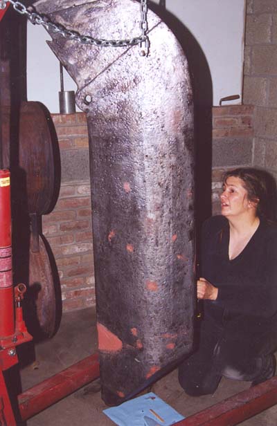
Refinishing the keel surface
The keel is cast iron coated with epoxy.
If the finish is sound but for a few spots, they can be sanded and built back up
with epoxy.
If the coating has lost integrity and the cast iron is rusting underneath it,
the keel wants to be sandblasted clean and recoated with two-part epoxy.
If only coating were necessary, we would have tried powdercoating instead of the
two-part, but the keel is a rough, rather crude casting and some fairing of the
surface will probably be required.
Two-part epoxies suitable for this job include the
Interlux InterProtect epoxy primer,
and the WEST System
family of epoxy and additives.
Either way, you start with a base coat of unthickened epoxy, then use
epoxy thickened as a fairing compound to fill pits and low spots.
In the Interlux world the fairing compound is a separate product; in the WEST
System you make your own by stirring some thickener into the epoxy.
You finish off with several coats of epoxy modified for better moisture
exclusion.
The InterProtect, which is gray, is already formulated as a moisture barrier;
in the WEST System you mix the epoxy with a barrier additive, which makes it
gray.
The barrier additive, which seems to be aluminum powder and mica flake in both
families of product, also adds abrasion resistance, not a bad thing for a keel.
You follow the cured epoxy with your favorite color and formula of bottom paint.
If you keep the boat out of the water and want to forgo the bottom paint, you
might use topside paint or just leave the epoxy exposed.
In that last case, the keel will wind up whatever color you like as long as it
is gray.
Exposed epoxy deteriorates under UV, but the keel is in the shadow of the boat
and trailer and the aluminum powder also adds some UV resistance, so it might
hold up OK.
You can get a white pigment additive for WEST System epoxy, but it is intended
only as a neutral base for later color coats, not to serve as a top coat on its
own.
Because we already had WEST System products around the house, we went WEST
instead of Interlux for the epoxy coat.
Over the epoxy we went with
Interlux MicronCSC multiseason ablative bottom paint in a
color called "shark white" which turns out to be ... gray.
At least it is a lighter gray than the epoxy coating, so we will be able to tell
when the bottom paint has ablated away.
The first coat
The very first coat of epoxy wants to bond to cast iron cleaned down to white
metal.
The cast iron, of course, begins oxidizing immediately.
Both Interlux and WEST System recommend strict measures to give the epoxy good
metal to bond to.
Interlux InterProtect must be applied within one hour of
sandblasting; or, failing that, a coat of VinyLux primer (a three-can
proposition) must be applied first.
WEST System epoxy should be applied as soon as possible after sandblasting, and
then the metal freshly abraded through the wet epoxy, using
sandpaper or a wire brush.
Abrading through a wet epoxy coat prevents oxygen from reaching the fresh metal
thus exposed, so the epoxy bonds directly to the metal.
On a surface as rough and pitted as the keel, a wire brush works better than
sandpaper.
If you take the keel to a sandblasting service, you might ask if they will let
you apply the first epoxy coats in a corner of their shop as soon as they are
done blasting, so you can get the
epoxy on as quickly as possible and without transporting the clean iron through
the weather.
When you ask, make it clear that you will need several hours to do the five
coats and fairing, and the keel will need 12 more hours or so of undisturbed
cure time before you can take it home.
Fairing
We started the fairing layer without waiting for the first, unthickened, coat to
begin to gel.
One decision that needs to be made is whether the goal is to fair the keel to
mirror quality or just to fill in the grossest imperfections.
Anungoday is used for cruising, not racing, so we took the second approach,
applying the fairing reasonably smooth with plastic scrapers and then moving
right on to the remaining epoxy coats.
That way, none of the epoxy had to reach full cure and all of our epoxy layers
are chemically linked in primary bonds.
More fastidious fairing would have called for letting the fairing compound fully
cure, then sanding it smooth, and the subsequent epoxy layers would only adhere
by secondary bonding.
Also, that would have taken more time and this was a long project anyway!
In the first picture below, you can see a large V of pink fairing compound near
the lower end of the keel.
This is where an alternate pendant attachment point is cast into the keel,
perhaps for use in the Balboa or RK boats.
On our Ensenada it was filled with fairing compound when we found it, and we did
the same thing.
Painting
Once the last coat of epoxy has fully cured, it can be roughed
up to support mechanical bonding of the first coat of paint.
Since we did not bother to fair the surface absolutely smooth, a wire brush
again works better than sandpaper at roughing up all the epoxy, even in the low
spots.
We applied the first coats of bottom paint with the keel hanging on the hoist,
saving enough to do final coating after the keel got put back in the
Keel-O-Matic and back into the boat, so the final coat at least would cover any
scrapes from handling in installation.
Renewing the pivot bearings
Cliff Unruh has a nice
diagram of the swing keel
pivot, and his
Common Balboa 20 Repairs page suggests a couple different techniques for
renewing the holes in the keel trunk that bear the pivot bushing, depending on
how worn they are.
We chose the less-intensive renewal process, leaving as much as possible of the
good original laminate intact.
We ground the holes with a Dremel sanding drum into some semblance of roundness
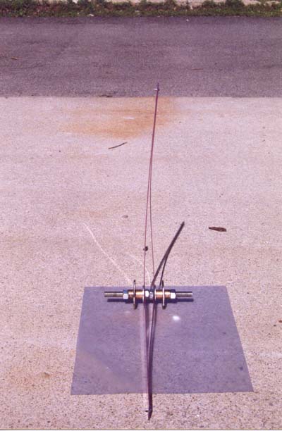
or at least smooth ovality, after using the two-axis square contraption shown in
the picture to locate where the final 3/4" holes needed to wind up on both sides
of the keel trunk, and marking those locations on the trunk.
The bores were wet out with neat epoxy, then built up with thickened epoxy and
circumferential ribbons of glass cloth until they were near the final locations
and slightly larger than the final size.
Then we cast the final bearing surfaces out of epoxy thickened with a 50/50
mixture of colloidal silica and graphite powder.
The bearing-forming contraption
All of these should be readily available at the hardware store.
- 1
- piece 1/2"-13 allthread, a few inches long
- 2
- 1/2-13 nuts
- 2
- 1/2" ID, 3/4" OD bushings or bronze bearings, longer than the keel
trunk laminate is thick
- 2
- 3/4" ID, large rubber washers
- 2
- 1/2" ID, large metal washers
- 4
- 18" x 1" flexible plastic rulers, or 2 18"x2" cut in half
- 2
- 1/2-13 jam nuts (these are thinner than your ordinary nut)
Make the four rulers into two ruler-V's.
Lay two rulers together flat and aligned, drill a small hole through both at one
end and clamp with a small screw.
That's the apex.
Keeping the rulers flat and aligned, drill a 1/2" hole through both at the other
end.
Such a ruler-V, with its legs spread a little bit apart as shown in the picture,
and clamped at equal length to avoid curvature (not quite as shown in the
picture), will be straight enough and stiff enough to align the bearings as
precisely as they need to be aligned.
Casting the bearings
- Wax all the parts of the bearing-forming contraption heavily to keep the
epoxy from bonding to them.
- Check that the bores, built up with epoxy and glass ribbons, are still
larger than the final size needed, by making sure the 3/4" OD bushings will pass
freely all the way through them.
Grind (if they have fully cured) or smush (if they are still workable) until
the 3/4" bushings pass freely.
- From inside the cabin, begin passing the allthread into the keel trunk
through the pivot hole on one side.
- From below the boat, stick one of the ruler-V's vertically into the keel
trunk near the pivot point.
Now place over the allthread:
- A 1/2" ID large metal washer.
- One leg of one ruler-V.
- One leg of the other ruler-V.
- Both jam nuts, separated slightly so they don't, well, jam.
- The other leg of the second ruler-V.
- The other leg of the first ruler-V.
- The other 1/2" ID large metal washer.
Spin the allthread through so roughly equal portions stick into the cabin from
both sides of the keel trunk.
Turn the two jam nuts away from each other to clamp the metal washers out
against the inside of the keel trunk, tight enough so the contraption will hold
a position.
Point one ruler-V straight up into the trunk and the other one straight aft,
and adjust the position of the bearing contraption until the ends of both V's
are centered in the trunk.
- Apply some silica/graphite thickened epoxy to the insides of the bores.
- Slide the short 3/4" OD bushings onto the contraption, one from each side.
Be sure they are all the way in and tight against the metal washers inside the
trunk.
Any gap will leave you with a ridge to very carefully grind away.
- Fix the bushings firmly in position with the final two nuts.
Recheck the ruler-V's for alignment and tighten the jam nuts firmly.
- Take more epoxy/silica/graphite and work it into the bores
around the bushings as well as possible.
Leave liberal rings of epoxy around the outside edges of the bores.
- Slide the rubber washers over the bushings and snug up against the keel
trunk, trying to force as much of the epoxy as possible into the bores.
The rest will be formed by the washers into smooth
flat surfaces for the keel bolt
sealing washers to seal against.
- Allow the epoxy to fully cure.
- Disassemble the contraption.
This is where you find out if you waxed it well enough.
If the bushings are difficult to remove from the bores, just disassemble and
remove everything else.
If the allthread turns out too long to remove with the bushings in place, or one
of the nuts is too well epoxied in place, just take a hacksaw to the allthread.
- If the bushings were difficult to remove from the bores, press them out.
- Find the 3/8" bolt, nut, and nylon bushings that were used for driving the
keel pivot out.
- From inside the cabin, insert the bolt through the stuck bushing.
- From below the hull, place a nylon bushing over the bolt and into the stuck
bushing.
Start the nut on the end of the bolt.
-
Push the bolt back into the cabin so the nut is against the bushing.
Place a thick metal plate, flat tool handle, etc., into the keel trunk for the
end of the bolt to bear against.
-
Hold the nut with a wrench and, from inside the cabin, turn the bolt clockwise
until the bushing has been removed from the bore.
Repeat for the other side.
-
Carefully remove any ridges in the epoxy.
Sand the surfaces on the inside of the keel trunk roughly flat and parallel.
Measure the width between them and sand just enough to clear the width of the
keel.
(See below if you are also using epoxy in the keel pivot hole instead of a nylon
bushing.)
An epoxy keel pivot bushing
The pivot hole in the keel casting originally contained a nylon bushing.
Ours was not suitable for reuse.
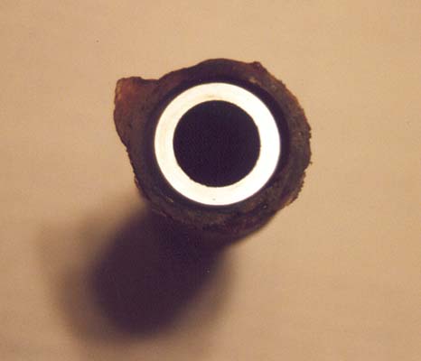
We had a new nylon bushing machined, but when we installed it in the keel, ran a
3/4" steel rod through it, and measured from the ends of the rod aft to the tip
of the keel, it turned out the bore was not true.
Removing the bushing, rotating it slightly, and replacing it did not seem to
change the angle, so we couldn't yell at our machinist.
(Well, we couldn't do that anyway, because he hadn't charged for the bushing.)
Perhaps the keel bore itself was either never straight, or corrosion had
affected it asymmetrically.
Anyway, instead of hauling the whole keel to a machine shop to see about getting
a bushing with a bore that would line up straight, we figured as long as the
keel trunk bearing surfaces are made of epoxy/graphite, it couldn't be too much
of a sacrifice of durability to fill the hole in the casting with the same
material.
For this job we mixed epoxy with 50/50 colloidal silica/graphite and added a
handful of chopped glass strands as suggested by a Gougeon Bros. technical
rep.
We suspended one of the 3/4" steel round rods centered in the keel pivot hole
supported by two bridles of string: one forward and up, hanging from the rubber
bumper dovetail, and the other aft and up, hanging from the bump around the
upper pivot hole.
These two bridles are very nearly orthogonal in the plane of the keel, and
adjusting them allowed us to hang the steel rod straight through the keel on
both the roll and yaw axes, checked with a tape measure from the rod ends to
reference points on the keel.
(It is much easier to fine adjust after packing the space around it
with epoxy/graphite mixture, dampening the motion.)
Be sure to wax the rod first!
Big 3/4" ID rubber washers slid over the rod ends and up against the keel helped
to force more epoxy into the bore, and form what stayed outside into smooth,
flat flanges.
After the epoxy cured, we twisted the rod to break it free, and pulled it from
the bore.
What we had then were very nice 3/4" bearing holes at both ends of the keel
bore, but some unfilled space in the middle.
The nicely formed holes at the ends served as guides so the bridles were no
longer needed to hold the rod in alignment, so all we needed to do was pack more
epoxy/graphite into the bore and stick the rod back through.
To best force the epoxy all through the voids, start by sticking the end of the
other 3/4" round rod into one side of the keel, no farther than the
depth of the nicely-formed part of the bearing, to act as a plug.
Fill the bore with epoxy/graphite and start the first round rod through from the
other side, forcing it against the plug until epoxy squishes out all around
both rods.
Keep forcing until the plug-rod is forced out and the end of the other rod is
just flush, then leave undisturbed while the epoxy cures.
Casting an epoxy pivot hole in the keel leaves you with nice epoxy flanges to
either side of the hole, just as you get epoxy/graphite flanges inside the keel
trunk.
You can measure the width between the keel-trunk flanges with a caliper, and
then sand down the keel flanges to the same width, to nearly eliminate side play
of the keel in the trunk and unsupported span of the pivot bushing.