In the last couple of years it has become possible to buy whole LED light assemblies designed for boats. We did Anungoday's cabin lights in 1995 before LEDs were so mainstream--you could say before they were cool, but LEDs can't help being cool. Even though the commercial, just-buy-it-and-plug-it-in options have since multiplied, we'll describe Anungoday's lights because there might still be some points that would make a custom approach worth considering.
Bare LEDs, resistors, and wire are cheap. LEDs "productized" for the marine market often are not.
It will take several individual LEDs to light a small boat cabin.
They can be clustered together in a traditional dome light fixture (usual for
the "products"), or you can string them along the edges of the cabin.
A traditional fixture has to be mounted somehow, screws or otherwise, to the
deckhead.
Individual LEDs are so small and light that it takes a dab of clear silicone, at
the most, to stick them wherever you want.
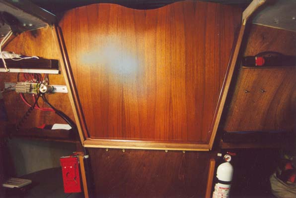
As Anungoday's main wiring duct runs along the edges of the deckhead, the LEDs
just stick out of it every couple of feet, with nothing else done to "mount"
them.
With their tiny, transparent lenses, they're almost invisible when they're not
turned on.
LEDs are different from incandescent bulbs, where you just provide some volts and you get light. LEDs need a resistor or some other regulator to keep them from drawing more current than they need (typically 0.02 amps). An LED just plugged into a voltage source lights up very brightly, but not for very long.
The need for current limiting seems like extra complexity, but has a silver lining, depending on where the regulator is put. The commercial products tend to be self-contained, with the resistor or regulator right there in the housing with the LEDs. The wiring from your distribution panel to the product is a generic unregulated 12V circuit like most others on your boat, subject to the same generic regulations, including a minimum size of 16 or 18 AWG (33CFR183.425d,e), which is a lot of copper to run for a circuit that needs less than a tenth of an amp, and takes up a lot of room in the wire run.
If you move the regulator back to the distribution panel, then the wiring from
there to the LEDs is a fractional-amp, current-limited electronic circuit.
An ordinary circuit with a fuse is not current-limited in the same
sense.
If overloaded or shorted, the ordinary circuit
will carry as much current as the battery can shove
through it, up to the time the fuse blows.
But the LED wiring after the resistor or regulator truly is limited to a small
current at all times, which makes it safe to use smaller, more convenient
wiring, as allowed by 33CFR183.425g.
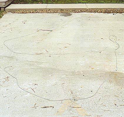
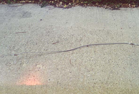
On Anungoday, a tiny ribbon of flat modular telephone cable encircles the cabin
with LEDs sticking out here and there.
The extra wires in the cable allow adding more LEDs (in sets of five red
ones or three white ones at a time) by just making small incisions in the
cable and soldering to the right wires--no new wire runs needed.
If you use individual fixtures and your lighting requirements call for more than one location, you're not going to do better than 0.02 amps per location. With a custom design, on the other hand, you can spread out the LEDs in one series strand so you have even lighting from multiple locations while drawing only 0.02 amps for the whole strand.
Anungoday's cabin lighting uses two strands of LEDs.
The first strand is of five red LEDs with three in the main
saloon and two in the vee berth.
A second strand is of three white LEDs in the main saloon only.
The white strand has its own switch, so the main cabin light dimmer brings up
either the red strand only, which will not clobber night vision, or dims the red
and white strands together.
When both strands are on and turned up full, the half-watt total power
consumption would take three months to drain the battery.
Of course the battery would have self-discharged long before that.
There is something that strikes me as slightly sleazy about the way LED light output is given in catalogs. It is usually given in terms of candela (cd), or rather thousandths of a cd (mcd). For example, the Chicago Miniature Lamp CMD333UWC, Anungoday's white light source, is listed on page 614 of DigiKey's on-line catalog for Q2 2000, at 2300 mcd. If you could compare that to something familiar like a light bulb, you'd have a grasp of how much light the LED produces. A General Electric 41026 (your basic 60W light bulb), for example, is rated at 865 lumens. But how do you compare mcd to lumens?
My old high school physics book has about a one page, really vague discussion of the candela and the lumen, and something called a solid angle, which is measured in steradians, and how a complete sphere is 4pi steradians, and a candela is the intensity of a source that gives off a lumen per steradian, that is, 4pi lumens. If you don't already know better, you can at least see the signs that something is missing in that brief description:
There's one little concept that was missing from my old physics book. If my LED looked like 2.3 candela no matter where you look from--that is, from anywhere on an imaginary sphere around it, then you could call it a 2.3 spherical candlepower light source. And if it were really 2.3 spherical candlepower, it would indeed be giving off 29 lumens. It would still be 2.3 S.C.P. if it were brighter from some directions than others, as long as the average (mean) were 2.3 cd over an entire surrounding sphere. Some small light bulbs are rated that way, in mean spherical candlepower (MSCP).
But not the typical LED. Instead, the LED throws a narrow beam in one direction, and if it is rated 2.3 cd, that means if you look from that direction you are looking at a 2.3 cd light source. From anywhere else, you are looking at a dim plastic blob with wires. It has 2.3 beam candlepower, but not 2.3 spherical candlepower, and the total light being produced is much less than 29 lumens.
If you want to know the total output in lumens of an LED, you need two things: the candela rating in the beam (2.3 cd in the example) and also the solid angle of the beam. The solid angle is just how much of the surface area of an enclosing unit sphere would be illuminated by the beam. Find the illuminated area in square units, and that number is also the solid angle in steradians. Multiply the candela rating by the steradians to get the lumen output. Of course if you light up the whole unit sphere (surface area of 4 pi square units), then the solid angle is 4 pi steradians, and that's why to convert from spherical candlepower to lumens, you can just multiply by 4 pi.
In an LED catalog, if you are lucky enough to find any description of the beam shape at all, it will almost certainly not be the solid angle in steradians, but rather a beam angle in degrees. Since the beam shape is pretty much a simple circular cone, it isn't a problem to convert. Just take the cosine of half the beam angle (be sure you know if your calculator or trig table is working in degrees or radians). Subtract it from 1, then multiply by 2 pi. The result is the solid angle (in steradians, regardless of how your calculator is set). Now you can multiply by the candela rating to get an approximation of the LED's output in lumens. The answer is approximate both because the LED's beam is not exactly the same brightness everywhere within the beam, and also because the beam doesn't really have sharp edges and total darkness around it. But at least you now have something to go on when comparing different LEDs to each other, or comparing an LED to something else you know.
On the same page of the DigiKey catalog is the Chicago Miniature CMD67-21UWC/TR8, with an intensity of only 150 mcd but a beam width of 120 degrees. Which one produces more light?
Solution. First find the solid angle of the first LED's beam. The cosine of 10 degrees (half the beam width) is 0.985, so 1 minus that is 0.015. Multiply by 2 pi to get 0.095 steradians. That solid angle, multiplied by 2.3 cd, gives about a quarter of a lumen (0.219).
Repeat for the second LED. Cosine 60 degrees (half 120) is 0.5 (might remember that one from trig class). Subtract 0.5 from 1 to get (surprise) 0.5 again, and multiply by 2 pi, to find a solid angle of pi steradians. Multiplying by 0.15 cd gives nearly half a lumen (0.47). The 150 mcd LED puts out more light than the 2300 mcd!
Probably not. Like many purveyors of LEDs, they aren't mentioning the beam angle in the catalog at all. When you see some enormous mcd figure and no information about the beam width, it's safest to assume the LED has a pretty narrow beam.
To really accurately measure the output of an LED, buy one and shine it on a photocell. Don does that a lot and has results for many different LEDs on his LEDs With Punch! page. The point of the calculations is to make informed judgments from the published specs before placing an order.
As far as the basics of making LEDs light up, I couldn't say it any better than Don Klipstein on his LEDs 101 page. One point he mentions, but only in passing, deserves more attention in the context of a small sailboat. With an LED, or a few LEDs, in series with a resistor, the same current (obviously) flows through the LED(s) and the resistor. Multiply that current by the LED voltage drop to get the watts of power getting to the LEDs to do useful work. The same current multiplied by the voltage drop across the resistor gives you the watts of power being spent to make a warm resistor. The way to minimize that waste, since you don't want to change the LED current, is to reduce the voltage drop across the resistor, and the way to do that is to stack more LEDs in series, so the total LED voltage drop accounts for more of the supply voltage, the resistor less.
There is a disadvantage, though, and it also is especially significant on a sailboat. The smaller the design voltage drop across the resistor, the more sensitive the circuit will be to variations in supply voltage. The deep-cycle batteries in a sailboat's house bank might be close to 13 volts when fully charged--even higher when charging--and be discharged down near 11 volts. You could design a string of six red LEDs (Vf of 1.9V, 11.4V total for six) that would work on a 12V supply with only 0.6 volts on the resistor. Unfortunately at a fully charged 13V they'd be overdriven by more than 100%, and during deep discharge they would dim greatly or go completely out.
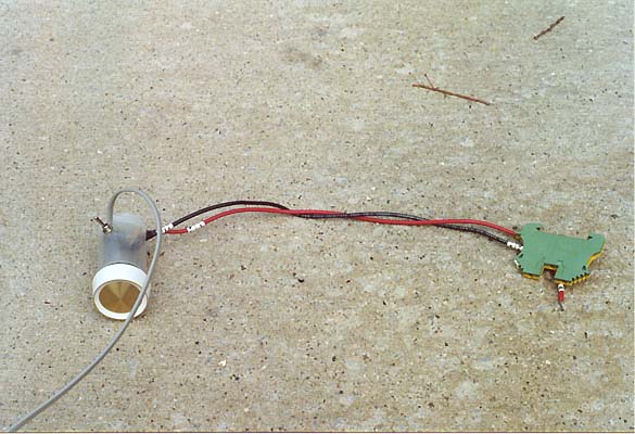
To get the low waste promised by more LEDs per strand, but avoid problems with varying input voltage, you can use an active regulator circuit instead of a simple resistor. If you build a regulator, it's not much more trouble to include a knob and have a dimmer. Here is the circuit we use on Anungoday. While the two strands of LEDs definitely produce no more than a modest amount of light, you might be surprised how often we turn the dimmer way down and do just fine with dark-adapted eyes. With eyes adapted, turning on the whites at full brightness can even hurt a little.
Real EE's might find this circuit to be a bizarre
design for a simple adjustable current regulator.
Rather than claiming there's anything great about it, let's just say it was
easy to design without having to remember too much from electronics class,
it has been working fine since 1995, and even if it's not as elegant as a
real EE might make it, it still fits in a 35mm film can.
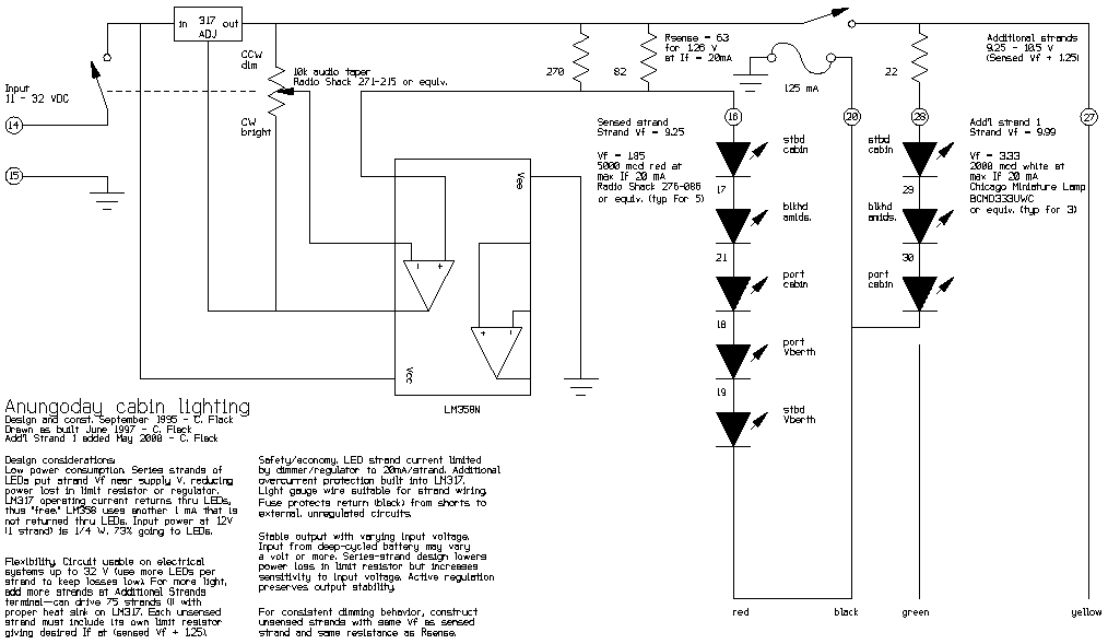
The four-conductor flat telephone cable used aboard Anungoday allows for one conductor (yellow, as drawn) to be used as a supply bus of regulated voltage for additional series strands of LEDs. For example, another strand of white LEDs could be added in the vee berth by just making some incisions, stripping some insulation from yellow without cutting it, soldering on another resistor and an LED, using segments of the green wire (which is unused past the location of the last white LED in the main saloon) between LEDs, and tacking the last LED cathode to the black return. Many arrangements (and lots of LEDs for lots of light) are possible with a physically small cable. If I had to do it again, though, I would use six-conductor phone cable, for more flexibility in, say, having both switched and unswitched additional strands, or interleaving different strands.
Each LED is just soldered to the appropriate conductors where a small incision has been made in the outer cable jacket. Then the whole site--LED, incision, and an inch or so of cable either side--can just be dunked in a can of clear Plasti Dip, which makes a tough, flexible, almost invisibly clear rubber coating with an insulation strength of 1400 volts per mil. For some reason the clear dip (my favorite) isn't stocked by retailers as often as the other colors, but the manufacturer will take your order and ship directly. I don't work for PlastiDip, but it sure is handy stuff. Get an empty paint can to store it in as it will solidify faster than you can use it up if kept in the original container. In a real paint can it keeps very well, especially if you pour in a jigger of naphtha now and then as the dip thickens with some inevitable evaporation whenever the lid is opened. Brushes clean up nicely in naphtha, as do booboos--or just let 'em cure and peel 'em off.
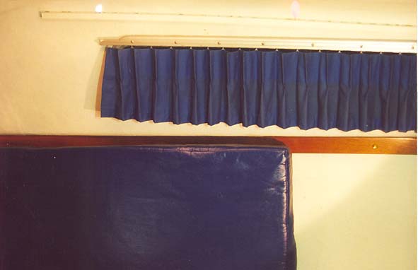
Aboard Anungoday, the assembled light cable runs with the other boat wiring in some Panduit Type F wiring duct. The duct runs high in the cabin, around the edge of the deckhead, where the wiring is easily accessible but the white, flush-style duct still looks quite nice. We used the 1/2" x 1/2" duct and would recommend, in hindsight, using at least the 1" x 1" even on such a small boat. Our small duct is now so full that adding another circuit would be a major chore, exactly what using duct was supposed to prevent. Avoid underestimating on duct size.
The small, flat lighting cable takes up very little space in the duct. Where the LEDs are attached, they just stick out through the slots in the duct. That's all the mounting they need.
For those who dislike the slotted look of duct, Panduit also offers unslotted surface raceway in a bewildering number of styles. With raceway you have to make your own slots wherever something needs to stick out, but the idea is otherwise the same.